On the Lighter Side of the Sun | By Piotr Mikus
After Dark (Series):
Browse the series: After Dark
Previous: Solar Street Light Dimming: One Pole Is Dim, the Next Is Fine
(What to demand in any solar all-in-one pathway or area lighting proposal when panel orientation is on the table):
- Panel azimuth documented separately from luminaire aiming direction, at the actual installed position
- Photometric submission based on the actual installed optic geometry, not a bench assumption where the panel and optic are both pointing the same direction
- Demonstrated RP-43-25 compliance at the actual installed orientation, not an idealized fixture position
- Energy harvest estimate using site-specific solar access data, with panel azimuth deviation losses stated explicitly
- Explanation of how the fixture maintains correct light distribution when the panel faces a direction other than the road
- Wind load and EPA calculation based on the actual installed panel geometry, not a simplified flat-panel model
There is a simple way to guarantee that a fixed all-in-one solar pathway light performs exactly as specified. Make sure every pathway on your project runs east to west. Mount every fixture on the north side of the path. Done.
If that sounds absurd, it is. But it is also an accurate description of the geometry problem built into most solar all-in-one luminaires available today. The sun does not reroute itself to match your pathway alignment. Panel orientation is a physics constraint. When that constraint is ignored in the design, you pay for it in one of two ways: lost harvest or compromised optics. Usually both.
Why panel orientation is a physics problem, not a product detail
A solar panel produces maximum output when it faces the sun directly. In the northern hemisphere that means orienting the panel toward true south. The tilt angle matters too, but for most pathway applications used primarily across the eight warmer months of the year, a standardized shallow tilt captures excellent harvest when sun angles are high. The variable that actually breaks most fixed all-in-one designs is azimuth. Any deviation from true south reduces the cosine component of incoming irradiation and shortens the effective charging window. This is not a footnote in the installation manual. It is geometry.
The numbers are not subtle. A 30-degree azimuth deviation from true south costs roughly 13 percent of daily harvest. At 45 degrees you lose about 30 percent. At 60 degrees you are down by half. A panel aligned parallel to a north-south running road is operating near the worst end of that range for most of the charging day. That is not a marginal rounding error in the energy budget. It is a structural gap between what the proposal promised and what the site actually delivers.
The two choices fixed geometry forces, and why both are wrong
A fixed all-in-one luminaire integrates the solar panel and the LED module into a single rigid assembly. The panel azimuth and the luminaire aiming direction are mechanically linked. You can set one correctly. You cannot set both.
Choice one: orient the fixture so the LED optic faces the pathway correctly. The panel now points wherever the road points. On anything other than a true east-west corridor, the panel azimuth is off. Each pole harvests a different amount of energy depending on which direction that stretch of path happens to run. The energy budget is built on assumptions that do not match the site.
Choice two: rotate the assembly so the panel faces roughly south for better harvest. The LED module has rotated with it. The optic is no longer aimed at the pathway. Light distribution degrades and glare increases. Neither choice is acceptable, and on a winding path you end up with both problems at once — different poles rotated to different angles, each one compromised in a different way.
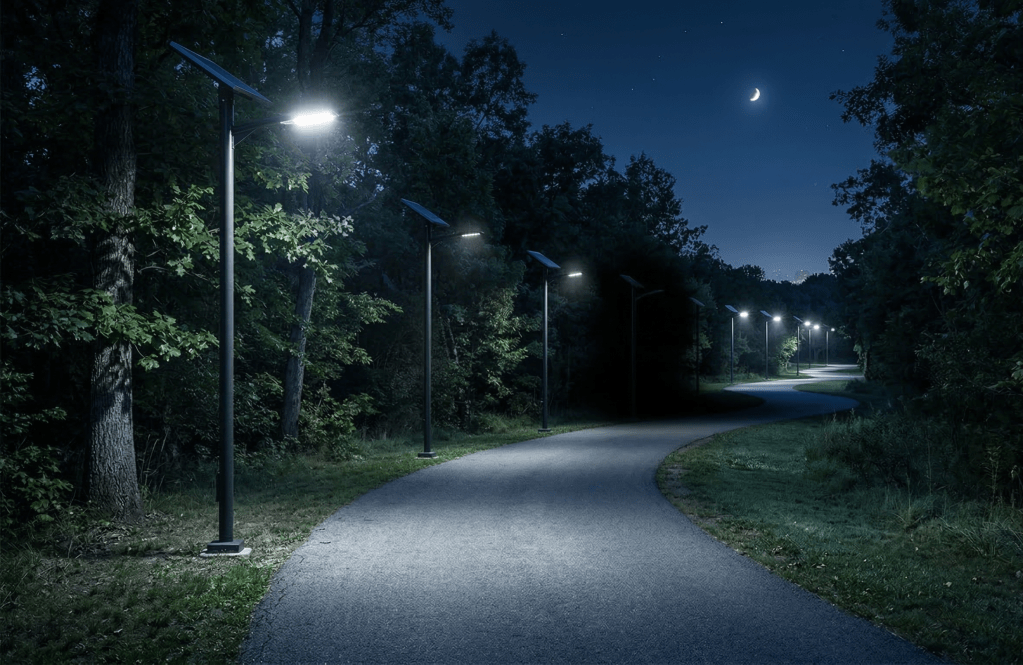
Here is what that looks like at 1 a.m. on a winding pathway. The IES file you reviewed at bid stage shows a perfectly performing fixture at full output with a fully charged battery. That is the best-case snapshot. In the field, each pole on a winding path faces a different azimuth. Each one harvests a different amount of energy every day. Each one reaches its battery protection threshold at a different time of night. One dims at midnight. The next stays on until 3 a.m. The one after that cuts out entirely by 11 p.m. The result is not a lit pathway. It is a patchwork of bright spots and dark gaps, and the dark gaps are exactly where a pedestrian is most exposed.
The optics problem is secondary to this. An off-axis luminaire is a problem. A dark luminaire is a safety failure.
Why oversizing the panel is not an answer
The common workaround is a larger panel. If the azimuth penalty is 30 percent, use a panel 30 percent bigger. The energy budget balances on paper again.
The problem is that this only addresses one of the two failures. A larger panel on a misaligned fixture still delivers the wrong light distribution. If the assembly is rotated for better harvest, the optic has rotated too. A bigger panel does not fix glare. It does not restore the photometric distribution the IES file describes. It does not make the installation compliant with RP-43-25 in any condition where the road runs in the wrong direction.
It also adds cost in ways that compound. A larger panel means more surface area exposed to wind. In off-grid lighting this is measured as Effective Projected Area, the cross-section the fixture presents to wind loading calculations. An oversized panel can double or triple the EPA compared to a properly sized design, which pushes pole wall thickness, foundation loads, and hardware costs upward. A fixture that should sit on a slender 12-foot pathway pole now needs a structure engineered for something much heavier. The workaround is more expensive than the problem it claims to solve, and it still does not solve the optical half of the problem.
What the IES file is not showing you
The photometric report you reviewed at bid stage shows the fixture at full output. Full battery, full harvest assumed, optic aimed exactly as tested. That is a single best-case snapshot. It tells you what the light looks like when everything is working perfectly on the best night of the year.
It does not show you what happens at pole three on a path that bends northwest, where the panel has been spending most of the day at 55 degrees off south. It does not show you pole seven where the path curves back east and the panel is doing slightly better but still not right. It does not show you what the corridor looks like at 1 a.m. when each of those poles, each with its own harvest deficit, hits its battery protection threshold at a different time and steps down or cuts out independently.
On a winding pathway with fixed all-in-one luminaires, the IES file describes a fixture that does not exist in the field. What exists in the field is a series of independent power systems, each harvesting a different amount of energy depending on which direction that section of path happens to face, each dimming and cutting out on its own schedule. The path does not go dark uniformly. It goes dark in patches, and those patches move around night to night depending on recent weather. That is not a lighting system. That is a liability.
What a properly engineered solar pathway fixture must actually be able to do
The geometry problem has a clean engineering solution. If the solar panel and the LED module can rotate independently of each other, both can be set correctly at installation. The panel faces south. The optic faces the pathway. The energy budget is built on real site-specific solar access. The photometric submission reflects the actual installed geometry. RP-43-25 compliance is demonstrated in the condition the fixture operates in every night, not the condition it was tested in on a bench.
Mechanical decoupling of the panel from the luminaire head is not a complicated concept. It requires a fixture architecture where the panel assembly rotates independently of the optic, each locked separately at installation. What it eliminates is the forced tradeoff between energy performance and photometric performance. A fixed all-in-one forces that choice. A decoupled design removes it entirely.
The penalty for not having it is paid every winter, on every project where the pathway does not happen to run east to west. Which is most of them.
What to Require in a Specification
If these questions cannot be answered with documented numbers, the proposal is based on bench geometry, not installed reality.
- Panel azimuth documented as a separate value from luminaire aiming direction, referenced to true south at the proposed installation location
- Energy harvest model using site-specific solar access data, with azimuth deviation losses from true south stated explicitly and reflected in the worst-month energy budget
- Photometric submission generated at the actual installed optic orientation, not a standard horizontal bench position where panel and optic are assumed to face the same direction
- Demonstrated RP-43-25 compliance for illuminance, uniformity, and glare criteria at the actual installed fixture position
- EPA and wind load calculation based on the actual installed panel geometry and azimuth, not a simplified flat-panel assumption
- Written description of the mechanical means by which panel azimuth and luminaire aiming direction are set independently, including how each is locked at commissioning
Three Questions That Expose the Geometry Problem
These questions are polite. The answers are not always comfortable.
What azimuth does the solar panel face at this installation, and what is the deviation from true south?
If the answer is the same number as the luminaire aiming direction, the panel and the optic are locked together. That means one of them is wrong. On a straight path that is one problem. On a winding path it is a different problem at every pole.
On a winding pathway, what is the range of panel azimuths across all poles, and how does that affect the energy budget pole by pole?
A single energy budget number for the whole project assumes all panels harvest equally. On a winding path with fixed all-in-one fixtures, that assumption is false. Each pole has a different harvest rate. Each pole reaches its battery protection threshold at a different time. If the proposal cannot show pole-by-pole energy margin, it cannot show that the corridor stays lit through the night.
What does the corridor look like at 1 a.m. after a string of partly cloudy days?
The IES file shows full output on a full battery. The real question is what happens when batteries are partially depleted and poles start stepping down independently. If the answer is vague, the risk is not. A patchwork of dimmed and dark poles on a pedestrian pathway is not a performance variation. It is a safety failure.
Closing Thought
The IES file shows you one pole, fully charged, perfectly aimed, on the best night of the year. A winding pathway gives you twenty poles, each facing a different direction, each dimming on its own schedule. Spec the system for what the path actually looks like at 1 a.m., not what the brochure looks like at noon.
Sources and Where to Verify
- ANSI/IES RP-43-25 (2025): Illuminance criteria, uniformity requirements, and glare control for pedestrian environments — the standard that governs what the installed fixture must actually deliver in the field.
- NREL PVWatts Calculator (pvwatts.nrel.gov): Azimuth and tilt inputs allow direct comparison of south-facing vs. road-aligned panel orientations at any location. The harvest difference is quantifiable at the site level.
- NREL, Solar Radiation Research Laboratory: Background data on cosine correction for off-south azimuth and its effect on peak and seasonal energy harvest.
- IEC 61215 / IEC 61730: PV module performance and mechanical loading standards, referenced in EPA and structural loading assessments for integrated solar luminaires.
Piotr Mikus is a roadway lighting designer and specifier focused on solar powered street lighting and controls.
Quick FAQ
Why does panel orientation matter so much for solar pathway lights?
Because the solar panel only reaches its rated output when it faces the sun directly. Any azimuth deviation from true south reduces harvest through the cosine effect. On a north-south running pathway, a panel aligned with the road can lose 50 percent or more of its effective daily harvest compared to a south-facing installation. In winter, that loss combines with shorter days and cold battery behavior to produce early dimming and shortened runtime.
Can you just use a bigger panel to compensate for a bad azimuth?
You can compensate for the harvest loss with a larger panel, at the cost of increased weight, higher EPA, greater wind loading, and larger pole requirements. But a bigger panel does not fix the optical geometry problem. If the panel and luminaire are mechanically linked, rotating the panel for better harvest also rotates the optic off-axis, which degrades uniformity and increases glare. The workaround addresses only half the problem and adds significant cost and structural load doing it.
What does RP-43-25 require that pole-by-pole dimming on a winding path might fail?
RP-43-25 sets criteria for maintained illuminance and uniformity across the pedestrian environment. Those criteria apply to the corridor as a whole, not just to one pole at full output. When fixed all-in-one fixtures on a winding path each harvest at a different rate and dim independently, the corridor uniformity collapses long before any individual fixture technically fails. The standard requires maintained performance. A patchwork of partially dimmed and dark poles does not deliver it.
Also in After Dark:
Solar Street Light Dimming: One Pole Is Dim, the Next Is Fine
Solar Street Light Shading: Why It Causes Early Dimming (and How to Prevent It)
Solar Street Light Energy Budget: Monthly Harvest vs Load, Autonomy, and Recovery
