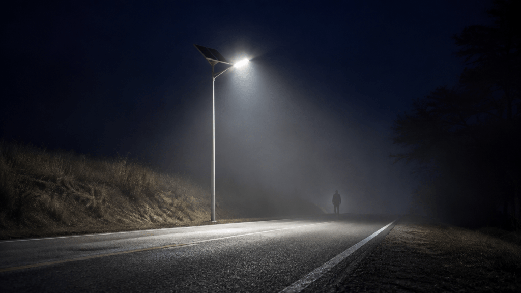
RP-8-25, Solar Edition | On the Lighter Side of the Sun | By Piotr Mikus
(What to demand in a specification before a submittal claims RP-8 compliance):
Veiling luminance ratio LV,max/Lavg calculated and reported per Section 3.5.1, with the design value stated against the classification limit
Maximum permissible veiling luminance ratio for the roadway classification disclosed per Table 10-1 or Table 11-1, not just referenced
Pole spacing to mounting height ratio documented, with LV,max/Lavg recalculated at the actual specified geometry
Arm tilt angle disclosed, with photometric recalculation performed at the specified tilt, not at the horizontal reference geometry
BUG rating per IES TM-15 reported at the actual installed tilt and mounting geometry, not the reference test configuration
High-angle candela disclosed for the proposed luminaire at vertical angles 72 to 88 degrees above horizontal, with peak value and peak angle stated
Observer position and geometry per Section 3.5.1: 83 metres ahead, 1.45 metre eye height, 1 degree below horizontal
Pavement classification R1, R2/R3, or R4 documented and used consistently across illuminance, luminance, and veiling luminance calculations
Section 6.10.2 compliance verified for LV,max/Lavg at every adaptive dimming level, not only at rated output
HOMER Pro sequential simulation confirming the veiling luminance criterion is maintained across every hour of every night of the design year
Table 10-1 has four columns. Solar submittals ship with one.
The other three exist. Sales just does not invite them to meetings.
The first column, average luminance, is the one everyone in the industry can quote from memory. The second and third columns, Lavg/Lmin and Lmax/Lmin, occasionally surface when someone with a red pen asks about uniformity. The fourth column, the veiling luminance ratio LV,max/Lavg, is the one that produces the long email silences described in the previous post. Not because the number is hard to calculate. Because in a solar constrained design, the number is hard to survive.
The Metric That Measures What the Driver Cannot See
The driver’s retina is the actual customer on a lighting project. Nobody put the retina on the distribution list.
Section 3.5.1 of ANSI/IES RP-8-25 defines veiling luminance LV as the luminance of a veil of light produced by scattered stray light inside the observer’s eye. It is not measured on the pavement. It is calculated at the driver’s eye position, from every source in the field of view above the horizontal, weighted by the geometry between the source and the eye. The result is a luminance value in cd/m2 that stacks on top of the background field. That added veil kills contrast. Killed contrast means the driver cannot see the pedestrian, the pothole, the dark object, or the deer, even while the pavement itself looks measurably bright in the isolux plot.
The ratio LV,max/Lavg is the enforced criterion. Table 10-1 gives a maximum permissible ratio for each roadway classification. Freeway Class A, 0.3. Major, Collector, and Local, 0.4. Exceed the ratio and the design fails RP-8. The pavement can look like a runway. It still fails.
Average luminance tells the specifier what the pavement is doing. Veiling luminance tells the specifier what the driver’s retina is doing. The submittal shows the first. The submittal skips the second. The retina files no complaint until somebody hits somebody.
The Solar Geometry That Spikes the Ratio
Every dollar saved on the battery is a candela added at 78 degrees. The dollar shows up on the invoice. The candela shows up in the police report.
Solar system cost is dominated by the panel, battery, mount, and foundation at each pole. The fastest way to reduce project cost is to reduce pole count. The fastest way to reduce pole count is to widen the spacing between poles. Wider spacing means each pole has to cover more pavement to hold the average luminance target. Covering more pavement from a fixed mounting height means the optical distribution has to throw further off axis. Throwing further off axis means candela climbs at high vertical angles, which is exactly the range Section 3.5.1 weights the heaviest.
The math is not up for debate. LV is driven by candela in the 72 to 88 degree band above horizontal. That band is where a stretched-envelope Type II or Type III optic has to put its usable light to reach the far end of the pole spacing. The wider the spacing to mounting height ratio, the more the fixture has to dump into that band. More light in that band means higher LV,max at the observer position. Higher LV,max means a worse LV,max/Lavg ratio. The ratio has a ceiling in Table 10-1. The ceiling does not care about the state of charge on your battery bank.
Grid-tied roadway design closes this gap with copper. Add a pole. Raise the mounting height. Tighten the optic. Solar cannot afford any of those three moves without redesigning the entire energy budget. So the fixture stays wide, the spacing stays generous, and the fourth column stays off the submittal.
The Distribution Class That Cannot Hide
Type II and Type III were sized for a spacing envelope. Solar keeps asking them to work outside it.
RP-8 classifies roadway distributions Type I through Type IV by the shape of the isolux pattern on the pavement, with a defined lateral throw and longitudinal reach for each. Type II covers narrow roads with the pole at the edge. Type III covers wider roads and is the workhorse for collector and arterial applications. Type IV throws forward and laterally, used on medians and offset arms. All three were characterised at a specific spacing-to-mounting-height ratio, typically in the 3.0 to 4.5 range depending on the classification and pavement class.
Solar street lighting keeps asking those same distributions to hold performance at spacing-to-mounting-height ratios beyond that envelope. Pole count is the dominant cost driver, so the sizing spreadsheet reaches for 5.0, 5.5, sometimes 6.0. The isolux pattern was never designed for that stretch. To hold average luminance at the extended spacing, the fixture’s usable output has to lean harder on the high-vertical-angle candela that carries light to the far end of the pole spacing envelope. That is the exact 72 to 88 degree band that Section 3.5.1 weights the heaviest.
The distribution type on the submittal is often correct. The spacing the distribution is being asked to cover is not. The average luminance number can still land, because the software will happily interpolate an answer at whatever spacing you type into the geometry field. The veiling luminance ratio quietly climbs while the average luminance column looks polite. Nobody prints the ratio, so nobody sees it climb.
And then there is the tilt angle party trick.
A growing number of solar fixture vendors have started marketing roadway solutions with aggressive upward tilt on the arm mount. Five degrees. Ten degrees. Occasionally fifteen. The premise is straightforward. Tilt the head up, throw the beam further down the road, stretch the footprint far enough to claim coverage across a three-lane roadway from a single pole. The isolux plot in the brochure looks fantastic. The battery bank did not have to grow. The spacing spreadsheet is thrilled.
A three-lane roadway from one pole because somebody tilted the fixture twelve degrees. Sure. Also the moon is made of tungsten.
Every degree of upward tilt rotates the entire candela distribution into higher vertical angles at the observer position. Uplight climbs. Backlight climbs. High-angle candela in the driver’s line of sight climbs the fastest of all. BUG ratings, per IES TM-15, collapse. BUG was engineered to reward fixtures that keep light on the pavement, out of the sky, and off the adjacent property. A fixture tilted fifteen degrees up throws light in all three of the wrong directions at once, and by design. The B score fails. The U score fails. The G score fails. And Section 3.5.1 does not read the marketing brochure. It just reads the candela at the observer angle and returns a veiling luminance number. That number goes up. Fast.
The submittal shows the isolux plot at the tilted geometry and calls the coverage a feature. The BUG rating at the tilted geometry, the LV,max/Lavg ratio at the tilted geometry, and the glare classification at the tilted geometry are all conveniently absent. If any of the three were shown, the design would fail RP-8 in three different sections before anyone finished checking the pavement class.
A specification that requires the fourth column of Table 10-1 forces the manufacturer to prove the chosen distribution can hold LV,max/Lavg at the actual specified geometry, at the actual specified tilt, not at the reference geometry the fixture was originally characterised at. Most cannot at extended spacing. Almost none can at extended spacing with an upward tilt. The compliant answer is tighter spacing, a taller mounting height that resets the observer geometry, a distribution reselection matched to the real project spacing, and an arm geometry that keeps the fixture horizontal or slightly downward. Every one of those costs the solar project money. So the geometry stays stretched, the arm stays tilted, and the fourth column stays swept.
The Adaptive Profile That Makes the Ratio Worse After Midnight
Dimming does not fix glare. It just turns the pavement darker while the glare sits roughly where it was. The math is embarrassing. That is why nobody publishes it.
Section 6.10.2 governs the operating floor. It does not govern only the illuminance floor. It governs the veiling luminance floor too.
An adaptive lighting profile that dims fixture output does not linearly scale the LV,max/Lavg ratio. Both LV and Lavg drop as output drops, but not at the same rate for every fixture. A wide-throw fixture with pronounced high-angle candela can hold a lower Lavg while LV,max drops more slowly, because the high-angle content is often the last thing to modulate in a given driver architecture. The ratio can get worse at reduced output, not better.
Manufacturer submittals never report LV,max/Lavg at the dimmed state. They report it at rated output, if they report it at all. Section 6.10.2 requires the criteria to be met at every operating level. That includes the veiling luminance ratio. The roadway classification does not permit the ratio to drift out of compliance at hour four because the battery started to sag. The driver still has to drive at hour four. The deer still has to be seen at hour four.
Why the Fourth Column Is a Solar Problem, Not a Grid Problem
Grid-tied fixes glare with copper. Solar fixes glare with an email that never gets answered.
A grid-tied designer facing a veiling luminance failure has three easy moves. Tighten the optic and add poles. Raise the mounting height. Compress the spacing. Every move costs materials and labour. None cost anything in energy. The grid does not have a state of charge.
A solar designer facing the same failure has none of those moves without redesigning the energy system. Tighter optics mean fewer lumens per pole, which forces larger panels and larger batteries at each pole to hold the same illuminance. Raising the mounting height means larger mounts, larger foundations, higher wind loads, and often a larger pole class. Compressing the spacing means more full solar assemblies, doubling the capital cost per linear foot. Every honest fix punishes the energy budget. The broom is cheaper. The broom is faster. The broom is what the customer thinks they are buying, whether they know it or not.
The fourth column is the load-bearing wall of the price on the sales sheet. Show it honestly and the price goes up. Sweep it and the price stays where the brochure promised. Guess which one the room votes for.
What to Require in a Specification
If the fourth column is not in the submittal, the standard was not honored.
Veiling luminance ratio LV,max/Lavg calculated and reported per Section 3.5.1, at the observer position and geometry defined in the standard, not the manufacturer’s default lab configuration
Pavement classification R1, R2/R3, or R4 documented and used consistently across the illuminance calculation, the luminance calculation, and the veiling luminance calculation
Arm tilt angle disclosed, with all photometric calculations performed at the actual specified tilt, not at the horizontal reference geometry
BUG rating per IES TM-15 recalculated at the specified mounting height, arm length, and tilt angle, with B, U, and G scores stated individually
High-angle candela values from the IES file disclosed at vertical angles 72 to 88 degrees, with the peak candela and the angle at which it occurs stated explicitly
Photometric calculation performed at the specified mounting height, arm length, and pole spacing, with LV,max/Lavg recalculated at the project geometry
Section 6.10.2 compliance demonstrated across every adaptive lighting level, with LV,max/Lavg reported at each dimmed state, not only at rated output
HOMER Pro sequential simulation confirming the veiling luminance criterion is maintained across every hour of every night of the design year, not only at hour zero on installation day
Fixture distribution type disclosed with written justification for the selection against the veiling luminance criterion at the specified spacing and tilt
Three Questions That Expose the Fourth Column
Ask them in an email. The reply, if it arrives, will arrive slower than a January sunrise in Winnipeg.
What is the calculated LV,max/Lavg ratio for the proposed design at the specified pole spacing, mounting height, arm tilt, and pavement classification, and how does it compare to the maximum permissible ratio in Table 10-1 or Table 11-1 for the roadway classification?
At the lowest adaptive lighting level defined in the operating profile, is the LV,max/Lavg ratio still inside the criterion, and where is that value reported in the submittal?
For the proposed luminaire, at the specified arm tilt, what is the peak candela at vertical angles between 72 and 88 degrees above horizontal, at what angle does the peak occur, and what is the resulting BUG rating per TM-15?
If the submittal cannot answer all three, the fourth column was swept.
Closing Thought
Average luminance is a marketing number. Veiling luminance is an engineering number. The first tells the customer the pavement is bright. The second tells the driver whether the pedestrian is visible. RP-8 requires both. Solar submittals ship one and hope the specifier does not read the standard. Read the standard.
Sources and Where to Verify
ANSI/IES RP-8-25 (2025), Part 1, Section 3.5.1 (Veiling Luminance)
ANSI/IES RP-8-25 (2025), Part 1, Section 6.10.2 (Adaptive Lighting Design Considerations)
ANSI/IES RP-8-25 (2025), Part 2, Chapter 10, Table 10-1 (Lighting Design Criteria for Highways)
ANSI/IES RP-8-25 (2025), Part 2, Chapter 11, Table 11-1 (Design Criteria for Streets, Bicycle Lanes, and Shared Streets)
IES TM-15 (Luminaire Classification System for Outdoor Luminaires, BUG rating methodology)
CIE 140 (Road Lighting Calculations), observer geometry and STV formulation
IES LM-63 photometric file format, high-angle candela disclosure conventions
HOMER Pro sequential simulation methodology (8,760-hour state of charge tracking and unmet load reporting)
Piotr Mikus is a roadway lighting designer and specifier focused on solar powered street lighting and controls.
Continue reading the series: https://solarlightingnightshift.com/category/rp-8-25-solar-edition/
Quick FAQ
What is veiling luminance?
Stray light scattered inside the driver’s eye that adds a luminous veil to the field of view, cutting contrast between the pavement and objects on it. It is calculated at the observer position, not measured on the pavement.
Why does solar make the ratio harder to meet?
Solar cost is dominated by the equipment at each pole. Wider spacing reduces pole count and cost, but wider spacing forces Type II and Type III optics to work outside their characterised envelope, throwing more candela at the high vertical angles that spike the veiling luminance ratio.
What is the problem with tilting the fixture upward on the arm?
Upward tilt rotates the entire candela distribution into higher vertical angles at the observer position. Uplight, backlight, and driver glare all climb. BUG scores per TM-15 collapse, and the veiling luminance ratio worsens, all in the same move. The isolux plot looks better on the brochure. The compliance picture looks worse across three RP-8 sections at once.
Can adaptive dimming push the ratio out of compliance?
Yes. LV and Lavg do not drop at identical rates when a fixture dims, and Section 6.10.2 requires the criterion to be met at every operating level, not only at rated output.

